Network Routing in Oracle Cloud Infrastructure
February 20, 2022
Oracle Cloud networking is mostly straightforward. But once your requirements expand and your network starts to increase in size, routing can be a little confusing. You may want to add security appliances, connect your on-premises environment, or establish connectivity between multiple regions. In this post, I’ll try to simplify and explain how network routing works in OCI. We’ll also take a look at a few possible routing scenarios.
I assume the reader has at least a basic understanding of networking and has enough knowledge about OCI.
The Basics
When creating a Virtual Cloud Network (VCN), OCI creates a default route table with no rules. Every subnet must be associated with one route table. If you did not select any during the subnet creation, OCI assigns the default route table. When a packet leaves a network interface, OCI tries to determine how to route this packet by inspecting the destination IP. If the destination IP falls under the same VCN CIDR, OCI tries to find the VNIC with that IP automatically. If OCI finds the VNIC, it delivers the packet to that interface. If no VNIC with the destination IP exists, OCI drops the packet. You cannot add a route rule with a destination CIDR that falls inside the VCN CIDR. You cannot modify the routing behavior for communication internal to the VCN. If the destination IP is outside the VCN CIDR, OCI searches the route table attached to the subnet of the source VNIC. If a matching Route Rule is found, OCI routes the packet to the destination of that rule. Otherwise, OCI drops the packet. Let’s take the following example network:
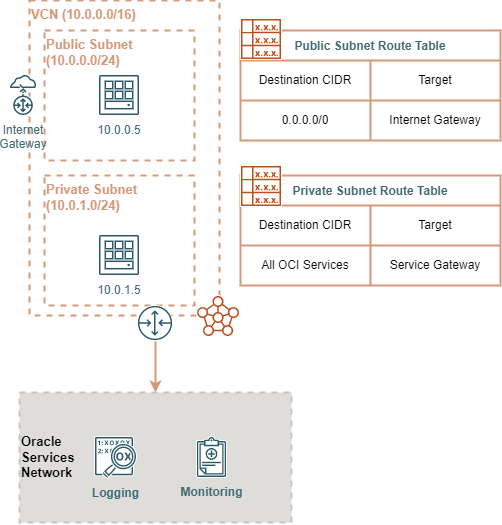
In the diagram above, we have a VCN (10.0.0.0/16) with two subnets inside it. One subnet is public, while the other is private. There is an internet gateway and a service gateway attached to the VCN. Let’s take two scenarios to show how routing works in practice. In the first scenario, The instance in the public subnet initiates traffic to the instance in the private subnet. OCI will inspect the destination IP and determine that the IP (10.0.1.5) is within the VCN CIDR. OCI searches for a VNIC with that IP. It finds it and delivers the packets to the instance in the private subnet. Notice that OCI did not look at the two route tables attached to the two subnets. In the second scenario, the instance in the public subnet initiates traffic to public service on the internet (17.5.7.8 as an example). Since the destination IP is not part of the VCN, OCI searches the Route Table attached to the subnet. A Route Rule with 0.0.0.0/0 destination CIDR with the internet gateway as the target. 0.0.0.0/0 CIDR means all networks. OCI then routes the packets to the internet gateway. You can apply the same principles when routing to a service gateway or a different VCN using a local peering gateway. Being equipped with the basic knowledge of how routing works in OCI, we can now explore some common network topologies and routing scenarios.
Routing Between VCNs Using Local Peering Gateway
A VCN is isolated from other VCNs by default. One option to connect two VCNs is by using Local Peering Gateways (LPG). To connect two VCNs using local peering, you must create a local peering gateway in both VCNs. Then you must configure route tables to allow subnets to route traffic correctly.

The diagram above is a simple local peering example. When a packet leaves Subnet-1 with a destination in Subnet-2, OCI will use the route table attached to Subnet-1 to route this packet to LPG-1. It is then routed automatically to LPG-2 and finally to its destination in Subnet-2.
Transit Routing Using Local Peering
The example above works fine in a small environment. But suppose you want to introduce a security appliance such as a next-generation firewall or an IPS appliance or use another load balancer appliance. The example above will not work in this case. Transit routing allows you to configure such routing scenarios. Transit routing provides a way to route traffic through an intermediate layer. You can use this routing pattern to create a hub-spoke network topology. To configure transit routing, you can associate a routing table to a local peering gateway. You can add a route table by expanding advanced options when creating or editing an LPG. Local Peering Gateways will use associated route tables to route traffic entering the VCN. It also has the same basic rules mentioned previously.
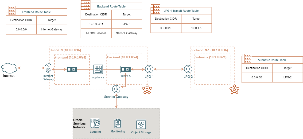
The diagram above is an example of this topology. For an internet user to access a service in the spoke VCN, the frontend interface will receive traffic from the user. The appliance NATs the destination IP to an instance in the spoke VCN and routes the traffic to the backend interface. OCI uses the backend route table to route the traffic to LPG-1 and finally to the destination VCN. If an instance in Subnet-2 wants to access the internet, OCI uses Subnet-2 route table to route traffic to LPG-2. LPG-2 steers the traffic to LPG-1. Since the destination is not a part of the hub VCN, LPG-1 uses the transit route table to determine the next hop. The next hop is the backend interface (10.0.1.5). The appliance NATs the private IP to a public IP and routes the traffic to the frontend interface. OCI then routes the traffic to the internet using the frontend route table. Note that this kind of topology has limitations. Each LPG can peer with only one VCN. The maximum number of LPGs for a single VCN is currently 10. Meaning for a single hub, you can have a maximum of 10 spokes.
Routing Between VCNs Using DRG
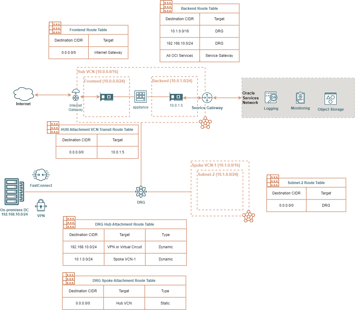
A dynamic routing gateway (DRG) provides more flexibility and simplicity. A single DRG can attach to multiple VCNs, IPSec tunnels, Virtual Circuits, and remote peering connections. It can import dynamic routes based on the policies you configure. Each DRG attachment has a DRG route table associated with it. When a packet enters the DRG, the DRG routes it using the route table associated with the DRG attachment. DRG route tables have two types of rules: Dynamic and static. Dynamic route rules are imported to the DRG route table depending on the attachment type and the Dynamic Route Import Distributions criteria associated with the route table. Static rules are created manually using the console or the OCI API. In VCN attachments, you can also associate a VCN transit route table. Unlike the DRG route tables, VCN route tables are created and managed in the VCN. You can use this to configure transit routing. The diagram below is an example.
As your environment increases in size, you may run into routing conflicts if you are using DRGs. Read the Oracle Documentation to understand how DRG attempts to resolve these conflicts and consider them during your network design.
Note that Oracle Documentation mentions that using DRGs to connect VCNs in the same region may come with increased latency.
There’s also a comprehensive example from Oracle Documentation.
Conclusion
Now you have a solid knowledge of how routing in OCI works. You can apply this knowledge to design, create and secure your OCI network. You can use the same principles to connect multiple OCI regions or connect to your on-premises network.